
How to suppress the generation of grinding cracks
The problem:
- Hard chrome layers and hardened parts are prone to grinding cracks during machining. By investigating crack formation in plane grinding processes of key aircraft actuator components—such as cylinders, pistons, and swash plates in pump structures—multiple improvements were attempted in grinding parameters, stress-relief processes, and overall process design. This study proposes general principles and specific methods for suppressing grinding cracks.
Cracking on Cylinder and Piston Surfaces: The inner bore of the cylinder and the outer circle of the piston are ground after being hard chrome-plated. The length of the grinding area typically exceeds 120 mm, with a post-grinding surface roughness of Ra 0.8 μm.
Compared to the inner bore of the cylinder, the outer circle of the piston has a higher probability of cracking.
This paper uses the piston as an example to discuss the suppression of cracking during the grinding of hard chrome layers. The common structure of the piston is shown in Figure 1. The grinding areas include the outer circle, end face, and root radius (R).
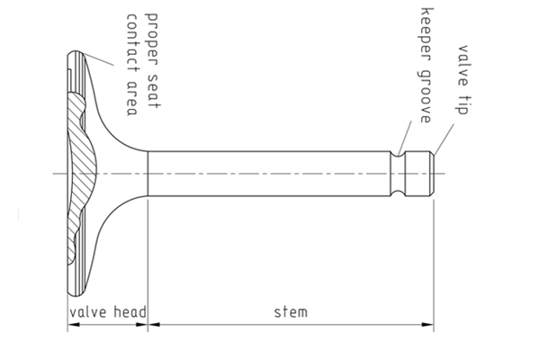
The piston component is hard chrome-plated on its outer cylindrical surface and root radius (R), with a coating thickness ranging from 0.08 to 0.15 mm.
The outer cylindrical surface requires a post-grinding roughness of Ra 0.4 μm, with a smooth transition at the radius (R). During grinding, the end face, radius (R), and outer cylinder are typically completed in a single operation.
The main parts of valve grinding include
– Valve cut off grinding
– Valve shaft centerless grinding
– Valve head & seat grinding
– Valve groove & tip raduis grinding
– Valve stem end grinding
– Valve seat grinding
Valve Disc end face grinding
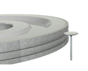
Metal CBN grinding wheel with fine grit is suitable for finish grinding the end face of vlave disc.

At a subcontractor’s facility, cracks frequently occurred in multiple batches after chromium layer grinding. The results of fluorescent penetrant inspection are shown in Figure 2.
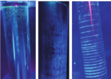
In Figure 2(a), cracks can be observed at the end face and the radius (R) region; in (b), rough, mudflat-like cracks are distributed across the entire outer cylindrical surface; in (c), circular chatter marks with regularly spaced cracks are present along the outer cylinder.
It is difficult to determine whether the cracks shown in Figure 2 originate solely in the chrome layer or are primarily grinding-induced.
To isolate the cause, components from the same plating batch were sent to different suppliers for grinding. The results confirmed that variations in the grinding process were the primary cause of cracking.
The pattern observed in Figure 2(c) is particularly indicative of grinding-related cracks, as chatter marks are a direct result of vibrational instability during machining.
Grinding Technology
The peripheral line speed of the grinding wheel is typically 35 m/s. The rough grinding parameters are as follows: workpiece rotation speed is (200–300) r/min, the transverse traverse rate of the wheel is 600 mm/min, and the radial infeeding amount per pass does not exceed 0.01 mm.
The fine grinding parameters are as follows: workpiece rotation speed is (100–200) r/min, the transverse traverse rate of the wheel is 400 mm/min, and the radial infeeding amount per pass does not exceed 0.005 mm.

The stock removal during fine grinding should not exceed 0.02 mm. A spark-out process follows, typically with no fewer than 6 passes. If the surface roughness after fine grinding measures Ra ≥ 0.4 μm, the number of spark-out passes should be appropriately increased.
In practice, it has been observed that the thickness of the hard chrome layer is not uniform across the entire plated surface of the component. Measurements taken with an outside micrometer and a dial indicator reveal the presence of localized high spots on the cylindrical surface.
Some high spots are located at the ends of the part, while others are caused by ovality of the cylinder. It is essential to begin grinding from the highest point.
The radial infeeding amount per pass must not exceed 0.01 mm until the high spots are removed or the coating taper/ovality is eliminated. Only then should the normal feed rate be applied. This prevents excessive depth of cut during initial contact with high spots, which would cause cracking. The grinding cracks present on the outer cylindrical portion in Figure 2(a) are a typical case resulting from this issue.
Improved Solution
Original Process Plan for the Swash Plate Component:
Hardening — Grinding the Plane by Supporting it on a Mandrel — Clamping with an Extension Arbor to Grind the Blind Hole — Stress Relief.
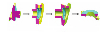
The process flow is illustrated in Figure 5.
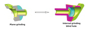
Grinding the plane by supporting it on a mandrel after hardening cannot completely avoid grinding cracks. Therefore, it was proposed to change the swash plate plane grinding to surface grinding performed after the hardening process.
The improved process plan is as follows:
Grind the plane by supporting it on a mandrel — Stress Relief — Boring — Hardening — Clamp with an extension arbor to grind the blind hole — Remove the extension arbor — Surface Grind the plane — Stress Relief.
The process flow is illustrated in Figure 6.
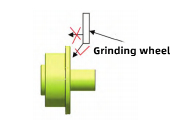
For the swash plate component, grinding the large plane by supporting it on a mandrel after hardening should be avoided. If this mandrel-supported grinding method must be used post-hardening, the allowable grinding stock must be strictly controlled. The removal amount should generally not exceed 0.05 mm. Furthermore, grinding must be performed using an angular infeed method; the grinding wheel’s flat face must not be directly applied to the workpiece in a perpendicular plunge grind. This can be achieved through appropriate CNC program settings, as illustrated in Figure 7.
Stress Relief Process after Hardening and Grinding
Post-grinding stress relief must be conducted within 8 hours after the hardening process. The recommended stress relief temperature is 140°C, with a soaking time of no less than 3 hours.
If the process is divided into rough grinding and finish grinding steps, stress relief treatment should be performed after rough grinding. Finish grinding is then carried out, followed by a final stress relief operation.
—EDITOR: Doris Hu
–POST:Doris Hu