

Research on the deformation behavior of CNC abrasive belt grinding of integral blade disc
.1 Grinding deformation mechanism of integral blade disc numerical control abrasive belt
The integral blade disc takes the blade and the wheel disc as a whole, and has the characteristics of thin blade, large bending and twisting, small blade spacing, and small curvature radius of the transition zone between the blade root and the edge. During the polishing of the whole blade disk, under the action of a large contact pressure, it is easy to cause double deformation of the blade and the abrasive system. In the whole blade disk abrasive belt grinding system, because the contact head of the grinding head is slender in the cantilever state Rod structure, the single blade of the whole blade disk is a thin plate structure with cantilever force, and the contact wheel is super-elastic material, so it is easy to produce weak rigid deformation under the action of grinding pressure. The weak rigid deformation model of the whole blade disk abrasive belt grinding system As shown in Figure 8.
grinding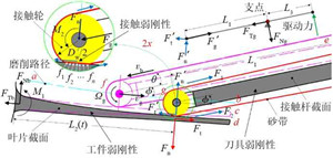
Fig. 8 Weak rigidity deformation model of belt grinding system
In the grinding of the blade surface of the whole blade disc, the thickness of the thinnest part of the blade is less than 1 mm, which is a typical thin-walled weak rigid part. At the same time, due to the narrow channel between the blades of the whole blade disc, it is difficult to design a tooling fixture that balances the grinding positive pressure for the grinding object, so that the workpiece undergoes weak rigid bending deformation of the ground part under the action of the grinding positive pressure. In addition, in order to fit complex curved surfaces, the contact wheel generally uses super-elastic materials, which can undergo different degrees of elastic deformation under the action of different grinding contact pressures, thus forming a weak rigid deformation between the belt and the workpiece.
2.2 Analysis of Grinding Deformation of Integral Blade Disk by CNC
The flow surface of the blade disc is deep and narrow. During the grinding process, the grinding belt contact wheel component needs to be deepened between the two blades. In order to avoid interference with other blades during the grinding process, the grinding area and the grinding area must be planned properly Grinding tool trajectory. Based on the analysis of the grinding deformation of the whole blade disk, the grinding parameters are optimized, and the reasonable grinding pressure is set in different grinding areas to achieve the precise removal of the grinding allowance, so as to realize the CNC belt grinding of the whole blade disk Cut processing.
ANSYS was used to simulate the grinding deformation of the blade back and leaf pot of the whole blade disc. The simulation results are shown in Figure 9 and Figure 10.
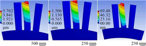
(a)Tip (b) Middle (c) Bottom
Fig. 9 Simulation of deformation during grinding blade back
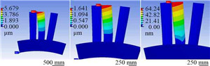
(a)Tip (b) Middle (c) Bottom
Fig. 10 Simulation of deformation during grinding blade pot
The deformation simulation results of blade grinding pressures of 10 N and 20 N are summarized in Fig. 11. It can be seen from Figure 11: With the increase of grinding pressure, the overall maximum deformation of the blade increases; under the same pressure, the maximum deformation of the blade tip, middle part and blade bottom decreases in sequence. The simulation results show that the maximum deformation of the blade tip is greater than the minimum blade margin of 0.005 mm, while the maximum deformation of the blade middle and the bottom of the blade is less than the minimum blade margin of 0.005 mm, and the bottom of the blade adapts to the changes in grinding pressure The ability is strong, so in order to reduce the deformation of the blade grinding process, a larger pressure can be used below the middle part of the blade, and a smaller grinding pressure above the middle part of the blade (grinding pressure should be less than 10 N). In addition, through the simulation results, it can be found that compared with the blade back grinding, the leaf basin deformation is slightly larger at the same location and the same pressure, so when grinding the leaf basin, the same grinding Select a slightly lower grinding pressure for the cutting position.
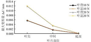
Fig. 11 Simulation results of blade deformations
at different grinding pressures
2.3 Grinding deformation control of integral blade disc CNC abrasive belt
After the overall blade disc is milled, the residual height of the surface texture is quite different. After the abrasive belt grinding, it is necessary to ensure that the residual height is completely removed and the consistency of the blade profile is ensured. Therefore, the grinding process The control of cutting deformation is crucial. The size of the grinding deformation depends largely on the size of the grinding pressure. The grinding pressure should not be too large, but it must be properly changed within a certain range to ensure that the grinding deformation and removal amount of different grinding areas meet the requirements. In order to meet the grinding requirements of the blade surface of the whole blade disc, a grinding pressure control system with pressure feedback is proposed, as shown in Figure 12.
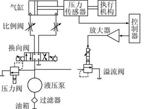
Fig. 12 Control system of grinding pressure
The pressure control system mainly includes fuel tank, filter, hydraulic pump, pressure valve, directional valve, proportional valve, cylinder, pressure sensor, controller, amplifier, overflow valve and other components. The controller is the core component of the control system, which can collect and process the feedback signal and send out the control signal to control the spool of the electric proportional valve to move, so that the gas flow into the cylinder changes accordingly. Through the change of the output pressure of the cylinder, the grinding pressure is changed within a certain range, and the grinding deformation is controlled to achieve the purpose of accurately removing the grinding allowance.
In the entire control system, the cylinder is the main output unit of the load, which is connected to the contact rod through the piston rod; the electric proportional valve is the key component connecting the cylinder and the controller. By setting the value of the electric proportional valve, the output pressure and input are changed The relationship of the signals; the grinding pressure can be measured by the pressure sensor. Through the analysis of the important variables of the control system, the mathematical model of the entire control system is obtained; according to the establishment of the control equations for the cylinder, electrical proportional valve and sensor, the block diagram of the control system shown in FIG. 13 is obtained; according to the transfer function of the cylinder, the electrical ratio The transfer function of the valve is combined with Fig. 13 to obtain the open-loop transfer function of the entire system. The control system can reduce the profile deformation caused by abrasive belt grinding, realize precise control of the grinding pressure, and ensure the surface quality and profile accuracy of the entire blade disc.
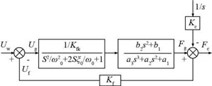
Fig. 13 Block diagram of control system


