

How do valves in an engine work?
The Valve is responsible for the input of fuel into the engine and exhaust gas. The valve is an important part of the car. The grinding part is the clamping groove of the air lock and the lug line. The quality of the valve plays a vital role in ensuring the efficiency of the engine. In order to ensure the processing accuracy of the valve, the outer diameter of the valve, the cone surface, the umbrella, the large end face and other surfaces are to be completed by grinding.
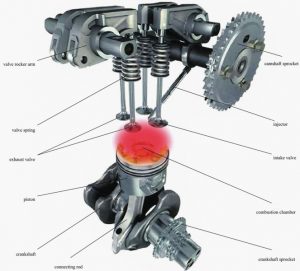
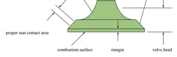
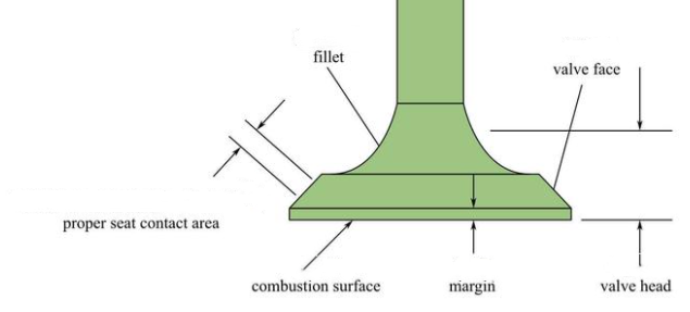
Valve is made of valve head, valve seat and valve stem three parts. The valve head is the entire lower area of the valve, with the valve face and inner rounded corners. The force produced by combustion pressure is applied here.
Valve head
The valve head temperature is very high (intake valve 570~670K, exhaust valve 1050~1200K), but also under the pressure of the gas, the force of the valve spring and the inertia force of the transmission component, its lubrication and cooling conditions are poor, requiring the valve must have a certain strength, stiffness, heat resistance and wear resistance. The intake valve is generally made of alloy steel (chromium steel, nickel chromium steel), and the exhaust valve is made of heat-resistant alloy (silicon chromium steel). Sometimes, to save heat – resistant alloys, the exhaust valve head is heat – resistant alloy and the rod is chrome steel, and the two are welded together.
The shape of the valve head is flat top, spherical top and horn top. Flat tops are usually used. Flat-top valve head has simple structure, convenient manufacturing, small heat absorption area, small mass, and intake and exhaust valves can be used. Spherical top valve is suitable for exhaust valve, which has high strength, low exhaust resistance and good exhaust gas elimination effect, but it has large heating area, large mass and inertia, and complex processing. Horn type has a certain streamline, can reduce the intake resistance, but its head heating area is large, only suitable for the intake valve.
Valve seat
The valve seat acts as a barrier between the combustion chamber and the air passage. In addition, heat is transferred from the valve to the cylinder head through this point. When the valve is closed, the surface of the valve seat rests with the cylinder head valve seat ring. There is no universal standard for the width of the valve seat surface. Narrow valve seat surface can improve sealing effect, but will reduce heat dissipation capacity. Generally, the intake valve seat with a smaller load is narrower than the exhaust valve seat with a higher load. Valve seat width is 1.2~2.0mm.
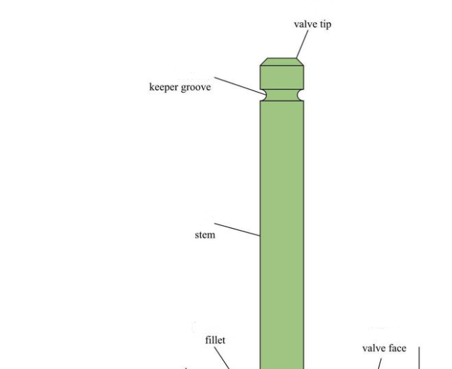
Valve stem
The valve stem is used to guide the valve in the valve guide. The valve stem is from the groove where the valve lock clamp is fixed to the transition of the inner fillet or the oil scraping edge. The valve stem is chrome plated to avoid valve stem wear.
The valve seat angle is the angle between the valve seat and a plane perpendicular to the valve stem. Sealing and wear also depend on the valve seat angle. For the intake valve, the valve seat angle will also affect the amount of fresh air intake, thus affecting the mixture formation process. In order to avoid valve seat wear, the surface of the valve seat should be armored. Here an armoring material can be fused to the valve seat in various ways.
Valve guide
The valve guide is used to ensure that the valve is centered in the valve seat and to transfer heat from the valve head to the cylinder head through the valve stem. Therefore, the optimum clearance between the guide hole and the valve rod should be left. If the clearance is too small, the valve will be stuck easily. If the clearance is too large, the cooling effect will be affected. It is best to leave as little valve clearance as possible. The valve guide is mounted in a pressure fit in the cylinder head. The valve duct should not be extended into the exhaust duct, otherwise the high temperature will cause the duct to be widened and combustion residue may enter the valve duct.
Valve lock clamp
The valve lock clamp is responsible for connecting the valve spring seat to the valve. The connection is divided into clamping type and non-clamping type. When the non-clamping connection is used, the two parts of the air lock clamps in the mounting state support each other. When clamping type connection is adopted, there is a certain gap between the two parts of air lock clamp after installation. The valve is clamped between the valve lock clips to prevent rotation. Clamped air lock clamps are especially suitable for high speed engines.
Engine intake valve and exhaust valve keeper groove, is not only the intensity of the valve stem weakness, and in the process of engine working, valve keeper groove in the valve springs, and other related parts, under the force of impact under high speed reciprocating load and alternating load, so the valve keeper groove machining precision by its significance. At present, the engine air keeper groove form has single groove and multi-groove form, in terms of the symmetry of the lock groove shape, there are symmetrical groove and asymmetric groove.

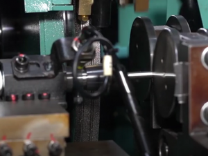
When the asymmetrical groove of the valve is strengthened by turning and rolling, due to the hydraulic strengthening process, the size control of the hydraulic margin of the valve keeper groove, and the asymmetry of rolling force. Factors such as imbalance, make keeper groove processing, there are many potential failure, serious when local metal tissue damage caused by valve keeper groove of the fracture, by contrast, asymmetric trough the implementation of form grinding, cutting, through grits, grinding force scatter distribution, high speed grinding to remove material, so as to improve the stress of the valve keeper groove machining.
In addition, many varieties of valves (including the valve with asymmetric groove shape of the keeper groove) contain the keeper groove in the quenching area of the rod end. Considering the stress effect of hot processing on the keeper groove, the keeper groove shape is often processed by forming the keeper groove grinding after quenching. Therefore, it is an effective way to ensure the machining accuracy of the air lock groove by using the forming grinding method of the valve keeper groove.
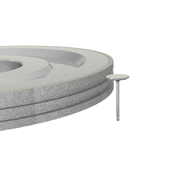
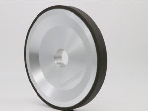
Valve keeper groove: CBN grinding wheel has the characteristics of high sharpness and wear resistance, high hardness and large grinding ratio. Engine valve grinding processes include external grinding, valve disc seat grinding, chamfering grinding, arc grinding and other parts.
Moresuperhard can provide completed grinding solution for valve rough, semi-finish and fine grinding, vitrified CBN grinding wheel ,metal diamond grindingwheel,elctroplated CBN grinding wheel used for valve parts processing.
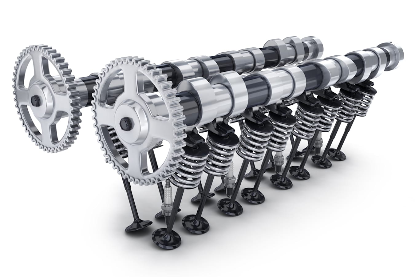
Valve springs
The valve spring is responsible for closing the valve in a controlled manner, which means that the valve must travel with the camshaft so that it can close in time even at the highest RPM. In addition, the force must be strong enough to prevent vibration after valve closure (also known as valve jump). When the valve is opened, the valve spring must prevent the valve from detaching from the CAM.
Intake and exhaust valves bear different loads. Both components move with the same load due to their inertia forces (about 300 million load changes over the life of the engine). But the exhaust valve is also heated by the exhaust gas, while the intake valve is cooled by the fresh air passing through it. Heat also diffuses from the valve through the valve seat as heat conduction.
The shape of the valve head is flat top, spherical top and horn top. Flat tops are usually used. Flat-top valve head has simple structure, convenient manufacturing, small heat absorption area, small mass, and intake and exhaust valves can be used. Spherical top valve is suitable for exhaust valve, which has high strength, low exhaust resistance and good exhaust gas elimination effect, but it has large heating area, large mass and inertia, and complex processing. Horn type has a certain streamline, can reduce the intake resistance, but its head heating area is large, only suitable for the intake valve.
Valve cone angle
The valve cone Angle is the Angle of the valve sealing surface, generally 45°, some 30°. 30° valve is considered lift the same situation, small taper valve, valve through the end face big, air intake resistance is small, but because of the small taper valve head margin thin, small stiffness, poor sealing and heat conductivity, commonly used for inlet valve General is 1 ~ 3 mm thickness on the edge of the valve, in order to prevent the work as the impact and the valve seat damage or by high temperature to burn out The valve rod is cylindrical and moves back and forth in the valve guide. Its surface must be superheated and polished.
—EDITOR: Doris Hu
—POST: Doris Hu


